APPLICATION>Bevel & Bevel-helical Gear Units
Bevel & Bevel-helical Gear Units
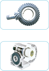
Bevel and bevel-helical gear units are designed for tough applications such as mining conveyors, paper mills, extruders, continuous casters or harbour cranes. They must provide high operational reliability in harsh conditions such as hot, humid and dusty environments, at very low speed and with heavy loads.
HCH bearings for bevel and bevel-helical gear units
By applying a systematic approach and modular thinking, HCH has developed advanced load and life calculation ways for bevel and bevel-helical gear units. Gear loads acting on straight tooth bevel gears and spiral bevel gears on cross shafts are shown in the pictures on the left side. In general, the relationship between the gear load and the pinion gear load, due to the right angle intersection of the two shafts, is as follows:
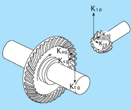 Ksp = Kag
Kap =Ksg
where,
Ksp , Ksg: Pinion and gear separating force, N
Kap, Kag: Pinion and gear axial load, N
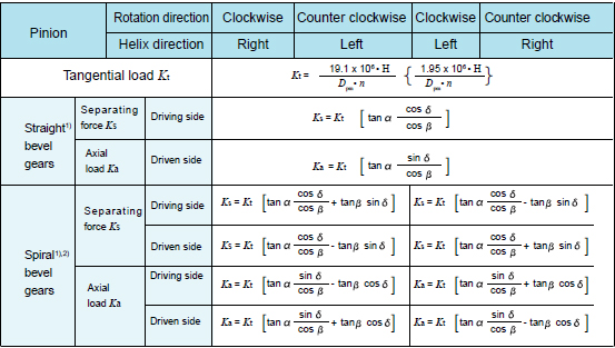
The calculation methods for these gear loads are shown in table as following:
Fig.4.4 Loads on bevel gears
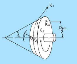 For spiral bevel gears, the direction of the load varies depending on the direction of the helix angle, the direction of rotation, and which side is the driving side or the driven side. The directions for the separating force (Ks) and axial load (Ka) shown in the left picture are positive directions. The direction of rotation and the helix angle direction are defined as viewed from the large end of the gear. The gear rotation direction in the picture is assumed to be clockwise (right).
Fig. 4.5 Bevel gear diagram
HCH bearings for bevel and bevel-helical gear units
By applying a systematic approach and modular thinking, HCH has developed advanced load and life calculation ways for bevel and bevel-helical gear units. Gear loads acting on straight tooth bevel gears and spiral bevel gears on cross shafts are shown in the pictures on the left side. In general, the relationship between the gear load and the pinion gear load, due to the right angle intersection of the two shafts, is as follows:
Ksp = KagKap =Ksg
where,
Ksp , Ksg: Pinion and gear separating force, N
Kap, Kag: Pinion and gear axial load, N
The calculation methods for these gear loads are shown in table as following:
Fig.4.4 Loads on bevel gears
|
where, Dpm :Mean pitch circle diameter, mm δ:Pitch cone angle |
Herein, to calculate gear loads for straight bevel gears, the helix angle β= 0. |
For spiral bevel gears, the direction of the load varies depending on the direction of the helix angle, the direction of rotation, and which side is the driving side or the driven side. The directions for the separating force (Ks) and axial load (Ka) shown in the left picture are positive directions. The direction of rotation and the helix angle direction are defined as viewed from the large end of the gear. The gear rotation direction in the picture is assumed to be clockwise (right).Fig. 4.5 Bevel gear diagram


As a rule, design engineers have only a few months to develop a new gear. Usually there is no opportunity to test a gear under field conditions before it is delivered to a customer. That is why the support of HCH is of particularly great importance.